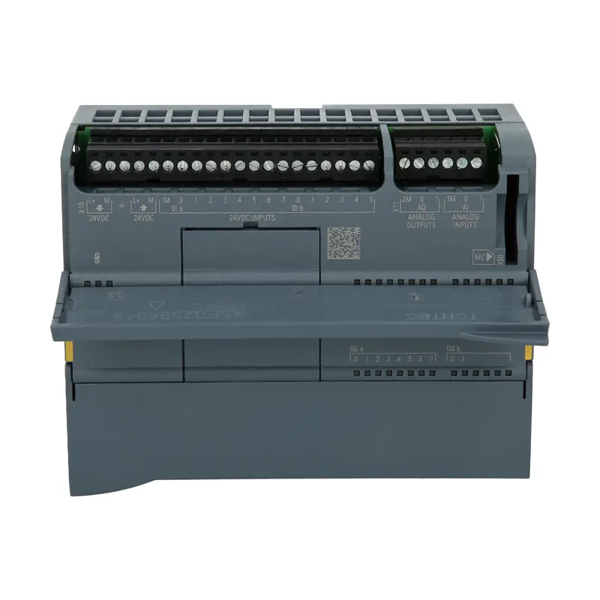
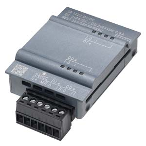
Key Features
Technical Specifications
General
Electrical
IO-Link Specifications
Digital Input/Output Specifications
Physical & Environmental
Pin Assignment
The SM 1278 IO-Link Master uses four connectors (X10, X11, X12, X13), one for each port. The pin assignments are :
Wiring Notes:
-
Connected IO-Link devices must use the device supply provided by the master module L connection
-
Use standard unshielded 3-wire cables for IO-Link devices
-
Maximum cable length is 20 meters
Applications
The SM 1278 IO-Link Master is ideal for applications requiring intelligent sensor and actuator integration:
-
Smart Sensors: Connecting IO-Link enabled proximity sensors, photoelectric sensors, and pressure sensors
-
Actuator Control: Controlling IO-Link valve terminals, motor starters, and signal devices
-
Process Monitoring: Reading parameters and diagnostics from IO-Link instruments (flow meters, temperature sensors)
-
Flexible Manufacturing: Reconfiguring ports between IO-Link, DI, and DQ modes for changing production requirements
-
Retrofit Applications: Adding IO-Link capability to existing S7-1200 systems without replacing the CPU
Key Benefits
Important Notes
-
Firmware Update Required for V2.1: The V2.1 firmware update (requiring TIA Portal V15 with HSP_V15_0257_001) adds configuration without S7-PCT, extended port qualifier, and master backup functions
-
Firmware Update Process: When updating via TIA Portal, two download cycles are required. Wait 15 seconds after the first download (DIAG LED flashes red) before repeating. Do not power off until the DIAG LED flashes green
-
S7-PCT Configuration: IO-Link parameterization typically requires the S7-PCT (Port Configuration Tool), STEP 7 Professional, and S7-1200 CPU V4.x or higher
-
Hardware Identifier: When using the IO_LINK_DEVICE function block, the ID parameter must be the hexadecimal hardware identifier of the specific port (e.g., 16#00A0), not the decimal master module identifier
-
Process Data vs Acyclic Data: Use the process image for cyclic measurement values; use IO_LINK_DEVICE for acyclic parameter reads
-
Cable Length Limit: IO-Link communication is limited to 20 meters with unshielded cable
FAQ
Q1: What is the primary function of the 6ES7278-4BD32-0XB0?
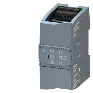
A: It is a SM 1278 4xIO-Link Master module that adds four IO-Link communication ports to SIMATIC S7-1200 PLCs. Each port can operate as IO-Link, digital input, or digital output, enabling integration of intelligent sensors and actuators .
Q2: What IO-Link protocol versions does this module support?
A: It supports both IO-Link protocol 1.0 and 1.1 specifications .
Q3: What transmission rates are available?
A: The module supports COM1 (4.8 kBd) , COM2 (38.4 kBd) , and COM3 (230.4 kBd) transmission rates .
Q4: How many IO-Link devices can be connected?
A: Up to four IO-Link devices can be connected, one per port .
Q5: What is the maximum process data size?
A: Each port supports up to 32 bytes input and 32 bytes output process data .
Q6: What is the maximum cable length for IO-Link devices?
A: The maximum unshielded cable length is 20 meters .
Q7: What are the physical dimensions and weight?
A: Dimensions are 45 mm × 100 mm × 75 mm with an approximate weight of 150 g .
Q8: What firmware update features are available in V2.1?
A: Firmware V2.1 adds configuration without S7-PCT, extended port qualifier function, and master backup capability .
Q9: What is the minimum supply voltage when IO-Link is used?
A: When IO-Link devices are connected, the supply voltage must be at least 20.5 V DC (compared to 19.2 V for standard operation) .
Q10: What is the difference between DI/DQ mode and IO-Link mode?
A: In DI mode, the port functions as a standard 24V digital input. In DQ mode, it functions as a 24V digital output (max 100 mA). In IO-Link mode, it enables full bidirectional communication with IO-Link devices .