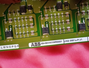
Product Details
Related Product Model Recommendations
| 3BSE081637R1 PM866AK02 |
PM860AK01 |
| 3BSE031155R1 BC810K02 |
BC810K01 3BSE031154R1 |
| 3BSE048845R1 CI868K01 |
TB840A 3BSE037760R1 |
| 3BSE043660R1 CI867K01 |
TU812V1 3BSE013232R1 |
| 3BSE018172R1 SB822 |
CI801 3BSE022366R1 |
| 3BSE037760R1 TB840A |
CI854AK01 3BSE030220R1 |
| 3BSE013210R1 DI830 |
PM891K01 3BSE053241R1 |
| 3BSE008510R1 DO810 |
PM866K01 3BSE050198R1 |
| 3BSE061637R1 TB826 |
PM862K01 3BSE076940R1 |
| 3BSC610066R1 SD833 |
DO820 3BSE008514R1 |
| 3BSC610067R1 SD834 |
AO810V2 3BSE038415R1 |
| 3BSC610068R1 SS832 |
TU810V1 3BSE013230R1 |
| 3BSE080239R1 NE870 |
TU811V1 3BSE013231R1 |
Payment & Delivery

FAQs

Q1: What is the primary function of the AINP-01C in the ACS800 drive?
The AINP-01C is the rectifier trigger board. It generates precisely timed PWM pulses (carrier frequency ~28.5 kHz) that fire the thyristors in the input bridge, converting AC to DC and regulating the DC bus voltage. It also manages the pre-charge sequence to safely charge the DC bus capacitors on startup.
Q2: How does the AINP-01C receive its "enable" signal to start firing?
On ACS800 drives, the AINT interface board sends a 24V enable signal through a V308 optocoupler to the AINP-01C. This happens after the control board (RMIO) successfully communicates with the AINT board during startup, ensuring controlled thyristor firing only when system conditions are safe.
Q3: Which ABB drive series is the AINP-01C compatible with?
The AINP-01C is primarily designed for ABB ACS800 series drives, specifically cabinet units with R8 frame sizes (and variants for R7, R9). It is also compatible with certain ACS850-04, ACS550-04, and ACS580-04 configurations where the BOM specifies this board.
Q4: Can the AINP-01C be used to retrofit or repair other brands of drives?
Yes. The AINP-01C's design—using 74HC423M monostable oscillators and LM339 comparators for synchronization—makes it versatile. With proper external circuitry (independent 12V supply, isolated enable control, and AC input connection), it has been successfully used to replace rectifier trigger boards in Allen-Bradley (Rockwell) and Schneider (Telemecanique) drives.
Q5: What should I check if the drive's DC bus voltage does not rise after applying main power?
Check the following:
-
AINP-01C board LEDs (if present) and physical condition (look for burn marks)
-
V308 optocoupler on the AINT board—confirm the 24V enable signal is reaching the AINP-01C
-
Input AC phases and fuses
-
Pre-charge circuit (charging resistors and contactor)
The AINP-01C is reliable but not indestructible—ensure the board's 12V supply and synchronization signals are intact.